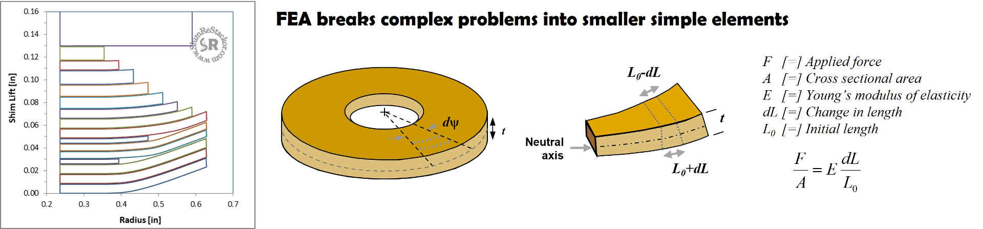
Shim ReStackor uses finite element analysis (FEA) to compute shim stiffness. FEA breaks down each shim into pie shaped segments and further divides each segment into smaller radial slices resulting in thousands of individual analysis elements. Shim stack stiffness is simply the sum of the combined FEA analysis elements.
The bending stiffness or each element is determined by defining a neutral bending axis. Bending the element compresses material above the neutral axis and stretches material below. Young’s modulus of elasticity defines the force required to stretch the material which in turn defines the bending stiffness of each element.
Shim stack structure deflection
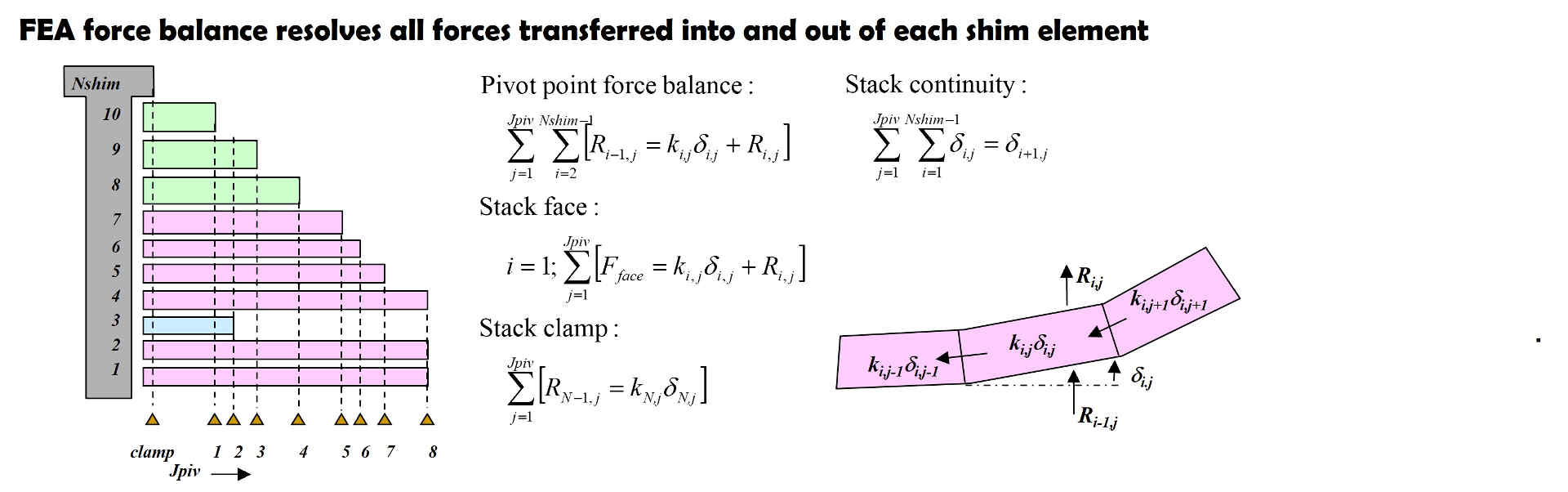
Force applied at the shim stack edge is transferred tangentially into adjacent elements on each side and transmitted radially into the shim center where the force is transferred into the shim stack clamp. Forces not reacted by bending are transmitted into the shims above.
Solving the bending deflection of the shim stack structure requires the solution of thousands of simultaneous equations balancing all forces transferred into and out of each FEA analysis element with the sum of all forces adding up to the force applied at the shim stack face.
Attempting to solve thousands of simultaneous equations by hand is nearly impossible. Fortunately, computers are extremely efficient at solving FEA problems and the GHz speeds of modern computers allows solution of complex FEA problems in a matter of seconds.
Shim ReStackor applies the capabilities of FEA to enable evaluation of complex shim stack structures using the simple inputs of shim diameter and thickness. That gives you the capability to fine tune damping force far beyond the limits previously possible through detailed control of the shim stack structural stiffness.
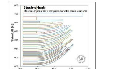
The capability of Shim ReStackor to resolve complex shim stack structures was tested using a random number generator to specify shim diameter and thickness. The stacks have no practical application other than demonstrating the capability of Shim ReStackor to resolve complex shim stack configurations with multiple crossover gaps and shim thickness changes creating a complex force transfer path from the face shim to the stack clamp.
Valve port fluid force on shim stack
Shim ReStackor defines the valve port geometry using three parameters.
- r.port: Defines the inside radius where fluid pressure is applied to the shim stack face
- d.port: Defines the valve port spoke length
- w.port: Defines the valve port perimeter seat length
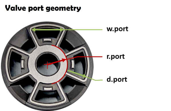
The combination of d.port and w.port define the valve port face area applying fluid pressure to the shim stack face creating the force deflecting the shim stack.
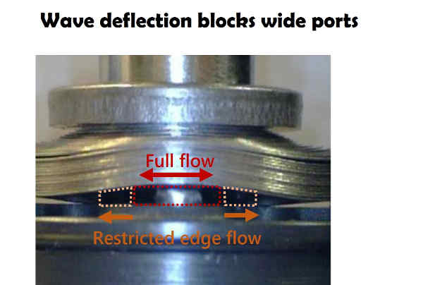
W.port also defines the pressurized perimeter length controlling the wave shaped tangential deflection of the shim stack. The wave shaped deflection partially closes off the left and right-hand portions of the valve port reducing the effective flow area on wide port valve pistons.
Shim stack flow area
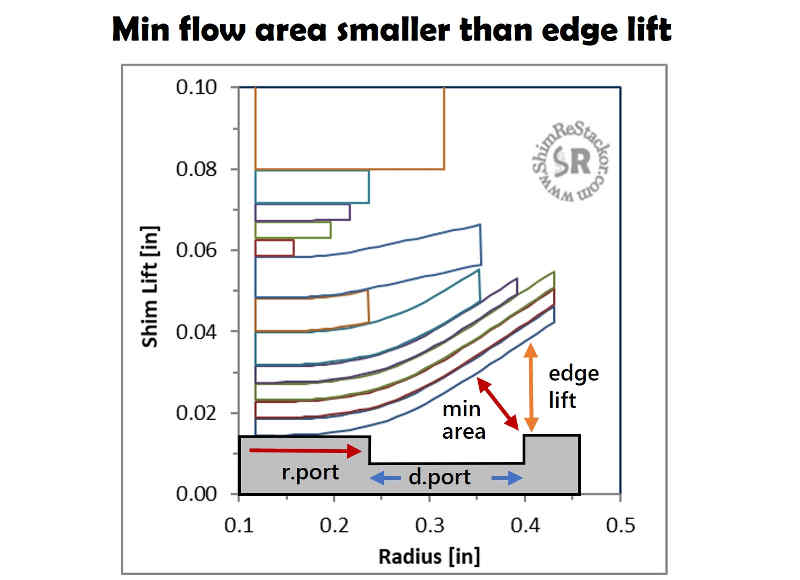
Shim stack stiffness is typically measured by edge lift at the valve port seat. However, the minimum flow area occurs on an angled plane measured normal to the face shim surface. The location of the minimum flow area plane changes with curvature of the shim stack face shim.
The fact that the minimum flow area does not occur at the valve port edge provides some insight into why direct measurements of edge lift, shim stack stiffness or shim factors poorly correlate with damping force produced by the shock absorber. Damping force is controlled by the minimum flow area, not shim stack edge lift.
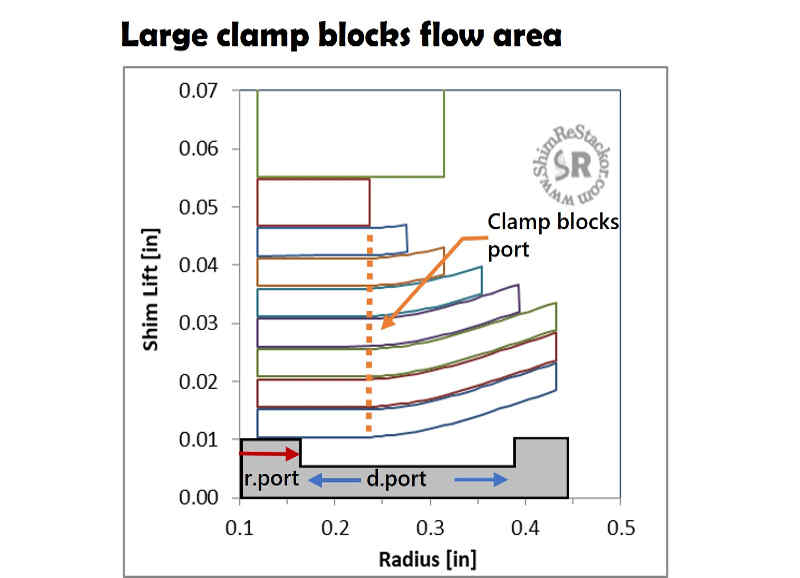
Stack clamp diameter
Increasing the shim stack clamp diameter increases the shim stack stiffness. Clamp diameters larger than two times r.port physically close off the inside portion of the valve port. Closing off a portion of the valve port generates damping force increases larger then expected by shim stack stiffness alone.
Dyno tuners often refer to the clamp diameter effect as an example of the highly nonlinear behavior of shim stacks. In reality, the nonlinear behavior is simply due to the large clamp diameters closing off a portion of the valve port. The Shim ReStackor r.port input accounts for the effect of large clamp diameters closing off a portion of the valve port.
Shim stack stiffness calculations verified through dyno testing
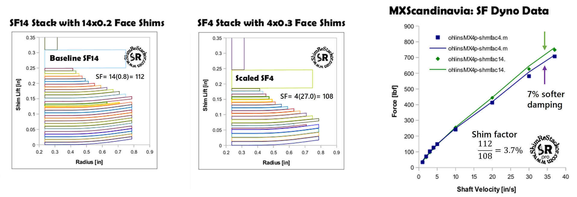
MXScandinavia on ThumperTalk dyno tested a series of shim stack configurations to evaluate the use of shim factors to estimate shim stack stiffness. The first test replaced fourteen 0.20 mm thick face shims (shim factor of 14*8=112) with a shorter stack of four 0.30 mm thick shims (shim factor 4*27=108).
By shim factor theory the replacement stack of four 0.30 mm face shims should be 4% softer. But that is only for the face shims.
When the face shims are combined with the high-speed stack the overall change in stack stiffness will be less than 4%.
Dyno testing the two shim stacks showed the shorter stack of four 0.30 mm face shims produced 7% softer damping, approximately double the difference expected by shim factors.
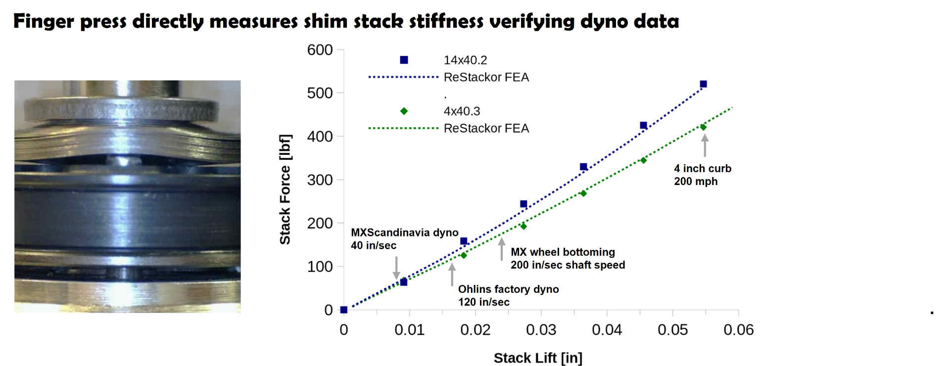
MXScandinavia took an additional step to quantify the shim stack stiffness difference and tested the two stacks on a finger press. A finger press inserts metal rods through the piston valve ports to directly measure the force required to deflect the shim stack. Using the finger press MXScandinavia determined the shorter stack of four 0.30 mm face shims was actually 17% softer than the original stack of fourteen 0.20 mm face shims.
Shim factor theory expected the stack of four 0.30 mm thick face shims to be 3% softer. The finger press measured the actual difference in stiffness to be 17%. The large difference in stiffness estimates is caused by friction between the shim surfaces.
The baseline stack of fourteen 0.20 mm face shims has fourteen friction surfaces. The sliding motion between shim surfaces as the stack bends adds to the stiffness of the shim stack. The replacement stack of four 0.30 mm shims only has four friction surfaces reducing the friction loss and the effective stiffness of the shorter stack.
Estimating friction effects is a complex problem as outlined in the Schnoor Belleville spring washer design handbook. FEA calculations in Shim ReStackor make the friction analysis much easier. FEA calculations determine the force transferred between each shim surface in the stack and that force directly defines the sliding friction and stiffness increase created by friction including the tapered section of the high-speed stack.
The MXScandinavia dyno measured damping force and Ohlins factory dyno data coupled with the finger press data demonstrate the capability of Shim ReStackor to match the shock absorber damping force while simultaneously matching the shim stack edge lift measurements made with the finger press.
The finger press also quantifies shim stack performance and edge lifts far beyond the limits of conventional dyno testing. The tested shim stacks were deflected to an edge lift of 1.2 mm. On a 3:1 leverage ratio motorcycle shock an edge lift of 1.2 mm is equivalent to hitting a six inch curb at 168 mph! Those shock velocities are well beyond any practical tuning range. Never the less, the data gives confidence applying Shim ReStackor at conditions well beyond the limits of conventional dyno testing.
Fine tune damping force far beyond the limits previously possible
Shim ReStackor uses a simple listing of shim diameter and thickness to specify the shim stack configuration. Thorough FEA calculations compute the shim stack stiffness and face shim deflection curvature giving an accurate and detailed evaluation of fluid flow area at the valve port.
Tuning shim stacks in software enables rapid shim changes and evaluation of damping force curves across the entire range of suspension velocities to perfect the shape and magnitude of damping force far beyond the limits previously possible .